
|
| Brand Name: | NUOYINGJIAYE |
| Model Number: | NYRD702 |
| MOQ: | 1 |
| Price: | $450 to $2000 |
| Payment Terms: | T/T |
| Supply Ability: | 1000 pcs/ pre month |
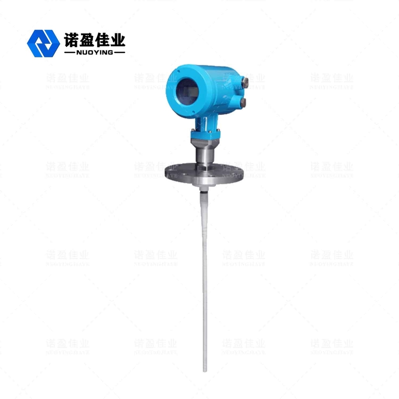
NYRD702 1.8GHz Guided Wave Radar Level Meter
The guided wave radar level meter is a level meter based on the principle of time domain reflection (TDR). The electromagnetic pulse of the radar level gauge propagates along the steel cable or probe at the speed of light. Part of the pulse of the level meter is reflected to form an echo and return to the pulse transmitter along the same path. The distance between the transmitter and the surface of the measured medium is proportional to the propagation time of the pulse during that period, and the liquid level height is calculated.
Radar Level Meter Technical Parameter
| Parameters |
Frequency: 100MHZ-1.8GHZ Measuring range:-cable :0-30m; rod, coaxial :0-6m Repeatability: ± 3mm Resolution: 1mm Sampling: echo 55 samples / s Response speed: 0.2S (depending on the actual usage) Output current signal :4-20mA Accuracy: <0.1% |
| Communication Interface | HART communication protocol |
| Process connection |
G1-1/2 Flange DN50, DN80, DN100, DN150 |
| Process pressure | -1 ~ 40bar |
| Power |
Power: 24VDC (± 10%), ripple voltage: 1Vpp Power consumption: max 22.5mA |
| Environmental conditions | temperature -40 ℃ ~ +80 ℃ |
| Housing protection grade | IP68 |
| Explosion levels | EXiaIICT6 |
| Instrumentation power supply and signal output wire connection |
Sharing a two-core shielded cable Cable entry: 2 M20 × 1.5 (the cables diameter of 5 - 9mm) |
※ Note: Products can be customized according to the specific requirements of users!
Radar Level Meter Operating Principle
Guided Wave Radar is the kind of measuring instrument that is based on the principle of time travel. The radar wave travels at the speed of light, and its running time can be converted into a level signal by the electronic components. The probe emits high-frequency pulses which spread along the cable, and the pulses are reflected back when they encounter the material surface and received by the receiver inside the meter. The distance signal is then converted to the level signal.
Radar Level Meter Design Features
◎ Guided wave radar level meter adopts advanced microwave processing technology and unique Echo Discovery echo processing technology, contact measurement, high measurement accuracy and more accurate measurement. At the same time, the guided wave radar is resistant to adhesion and is not affected by the external environment such as medium temperature and adhesion.
◎ A variety of process connection methods and types of detection components make 70X series guided wave radar level gauges suitable for various complex working conditions and applications. Such as: high temperature, high pressure and small dielectric constant medium.
◎ Using pulse working mode, the product has extremely low emission power, and can be installed in various metal and non-metal
containers without harm to human body and the environment.
Radar Level Meter Installation requirements
Measurement Range
Symbol explanation:
H---- Measurement range
L---- Empty tank distance
B---- The blind area at the top
E---- The minimum distance between the probe and the tank wall
The blind area refers to the minimum distance between the highest level of the material surface and the measurement reference point.
The bottom blind area refers to the distance near the cable bottom that cannot be precisely measured.
The effective distance is the one between the top blind area and the bottom blind area.
Note:Only when the material level is at between the top and bottom blind areas can a reliable measurement of the material level be guaranteed.
Radar Level Meter Electricalconnections
◎ Supply voltage
(4 ~20)mA/HART(Two-wire)
The power supply and the output current signal share a two-core shielded cable. Refer to the technical data for the specific supply voltage range. For the intrinsically safe type, a safety barrier must be added between the power supply and the instrument.
(4~20)mA/HART(Four-wire)
The power supply and the current signal are separated, and each uses a two-core shielded wire. Refer to the technical data for the specific supply voltage range.
RS485/Modbus
The power supply and the Modbus signal are separated, and each uses a two-core shielded wire. For specific supply voltage range see technical data .
Address
Block V5, Ronghao Industrial Town, Gaoling District, Xi'an City, Shaanxi Province
Tel
86-029-89303101